Troubleshooting tips for hydraulic systems
Table of Contents
Table of Contents
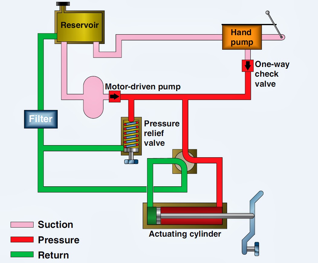
If you are in the field of hydraulic engineering, then being able to draw hydraulic schematics is a crucial skill to possess. A hydraulic schematic is a diagram that defines the flow of hydraulic fluid in a system. These diagrams are important as they show details about the individual components of a system, including the fluid supply, components and actuators.
Learning how to draw hydraulic schematics may seem daunting, especially if you are new to the field. However, it is an essential task that requires practice, patience and attention to detail. Whether you are trying to diagnose a problem or designing a new system, being able to read and create hydraulic schematics is an important skill to have.
The first step to drawing hydraulic schematics lies in understanding the fundamental symbols and components that make up the different parts of the system. You need to be able to identify components such as pressure relief valves, cylinders, and hydraulic motors, and understand how they relate to the system as a whole.
Once you have a grasp of the basic symbolic representations, you can start designing your hydraulic schematic. Begin by identifying the primary energy sources and focusing on the direction and flow of the fluid. It’s crucial to label every component of the system, including the pressure switches, flow meters, and other essential components, to ensure readability and ease of maintenance.
Drawing Effective Hydraulic Schematics
I took a hydraulic system maintenance course early in my career, and learning how to draw hydraulic schematics was part of the curriculum. One day in the classroom, the instructor drew a hydraulic schematic on the blackboard and identified each component one by one. Seeing each component come together to make an entire hydraulic system was an eye-opener for me.
Having a personal experience helps to understand the subject better. Drawing effective schematics requires knowledge of every component and their individual functions. It also demands attention to detail, accuracy, and the ability to visualize the entire system while working on a specific component.
The Best Tools for Drawing Hydraulic Schematics
Nowadays, drawing hydraulic schematics has become a lot more accessible, and you have a variety of software tools to choose from. There are software tools such as AutoCAD, Creo, and SolidWorks that can help you create precise hydraulic schematics and simulate system function, allowing you to catch any issues before the system is implemented.
However, for those who prefer a more traditional approach, pen and paper can be just as effective. Mechanical pencils and a good ruler can allow you to get all the details right while maintaining ease of readability. Whichever approach you choose, the fundamental element is your understanding of the hydraulic system’s components and functions.
Common Symbols and Combinations in Hydraulic Schematics
Hydraulic schematics contain a variety of symbols and combinations that are unique to the field. Some commonly used symbols in hydraulic schematics include the directional valve, cylinder, pump, and motor. A directional valve enables the fluid to change direction, while a cylinder converts hydraulic energy into linear mechanical energy.
In addition to these symbols, there are also several important combinations to be aware of. For example, a pressure relief valve can be depicted either on its own or in combination with a separate hydraulic component. The pressure relief valve reduces system pressure and protects components from damage by diverting fluid over a relief valve.
Benefits of Knowing How to Draw Hydraulic Schematics
Knowing how to draw hydraulic schematics can be beneficial in many ways beyond simply being able to understand hydraulic systems. You can use your knowledge to diagnose and troubleshoot problems issues, design systems, and interpret hydraulic schematics.
The ability to draw hydraulic schematics also allows you to communicate more effectively with other engineers, technicians, and personnel in the field. It allows you to deliver clear and concise information, leading to faster response times and fewer costly mistakes.
Question and Answer Section
Q: How can I improve my understanding of hydraulic systems?
A: You can improve your understanding of hydraulic systems by taking a course, attending relevant workshops, or doing research on the internet.
Q: What is the most common mistake made in drawing hydraulic schematics?
A: The most common mistake is inadequate labeling of parts and hose lines in the schematic.
Q: Can I use hydraulic schematics for maintenance purposes?
A: Yes! Schematics can help you diagnose problems and perform preventative maintenance.
Q: How can I ensure that my hydraulic schematics are accurate?
A: Taking measurements, getting feedback from colleagues, and using computer-aided design tools can improve accuracy.
Conclusion of How to Draw Hydraulic Schematics
Learning how to draw hydraulic schematics requires time, effort, and a desire to master the skill. But the rewards are many. With this knowledge, you can better diagnose issues, design systems more accurately, and communicate your understanding with your colleagues, leading to better and safer systems.
Gallery
Simplified Hydraulic Circuit Schematic For The Motor Efficiency Test

Photo Credit by: bing.com / simplified efficiency rig directional
Troubleshooting Tips For Hydraulic Systems - Womack Machine Supply Company

Photo Credit by: bing.com / hydraulic systems troubleshooting diagram system basic components typical womack tips machine supply data
Aircraft Systems: Basic Hydraulic Systems

Photo Credit by: bing.com / hydraulic basic system systems aircraft hydraulics diagram schematic valve flight figure open power pressure mechanic actuator center selector
HYDRAULIC SYSTEM FOR BEGINNERS | FUNDAMENTALS AND APPLICATIONS OF

Photo Credit by: bing.com / hydraulic symbols system engineering diagram circuit drawing mechanical simple beginners valve marine electrical pump solenoid systems applications industrial cylinder pnuematic
The Hydraulic Circuit Diagram Of A Plant With Two Actuators. | Download

Photo Credit by: bing.com / hydraulic actuators fig19 fluidics andrew


